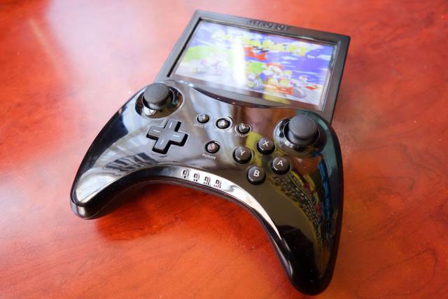
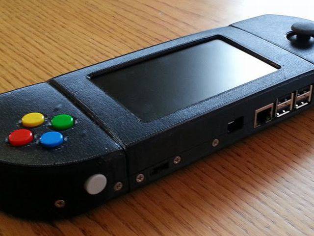
Finished product first!
I'm quite happy with how it turned out, considering all the little details behind the scenes to make it work... Here's the key features:
- Raspberry Pi 3 running RetroPie image
- Can emulate all the classic gaming consoles you can imagine up to & including the N64!
- Battery powered with rechargeable 2x 3400mAh Li-Ion
- 5" 800x480 screen
- HDMI output for playing on TV
- Stereo speakers and heaphone jack with volume control
- Battery power/charging indicator lights
- Teensy microprocessor to read button states and act as Joystick
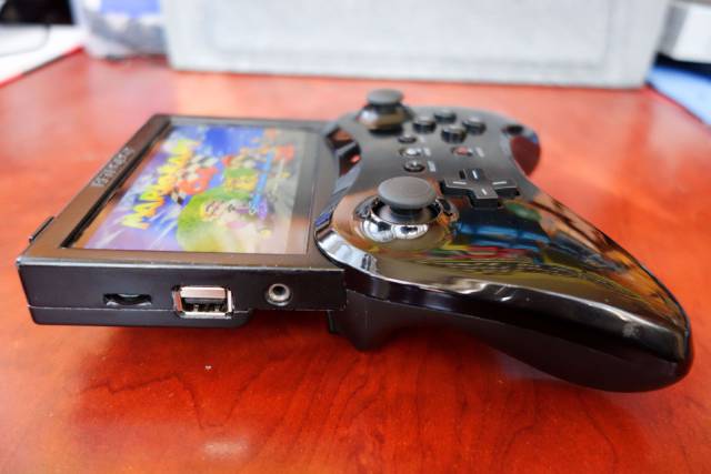
The Side
Here you can see the headphone jack, volume control wheel and a USB port
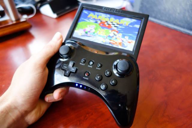
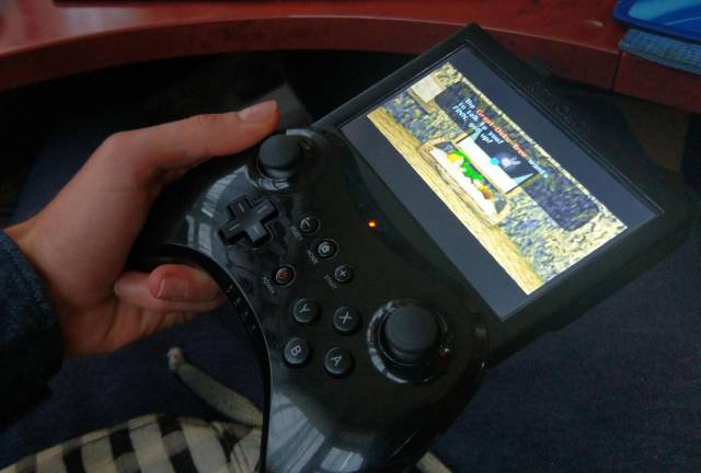
Hands on
The controller's player number indicators are used to show battery charge when Power button is pressed
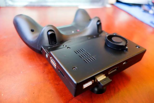
Underneath
The HDMI output, charging port and 2 more USB ports are on the top. Controller trigger buttons are intact!
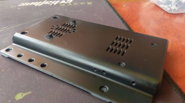
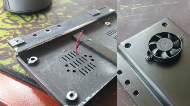
I had to install a small external cooling fan due to some unforeseen overheating problems I'll explain later..
How it all started
I've come across a few posts of people doing similar things with the Raspberry Pi and the RetroPie OS or similar, and there are quite a few write-ups of people following this recipe along with a fully 3D-printed body, or putting it inside and existing Gameboy.
Originally I planned to go for the completely custom 3D printed body because it allowed more flexibility and control over design. I started to order parts including a 5" screen and a bunch of cheap console controllers from eBay to salvage parts from (like the buttons) or use as external controllers for multiplayer games.
Then when I got one of the knock-off Wii Pro controllers in my hand I realised I probably wouldn't be able to design and create something this sleek and ergonomic.. I held the screen to the top of the controller and then I knew exactly what had to be done!
It's meant to be!
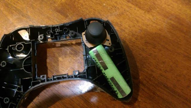
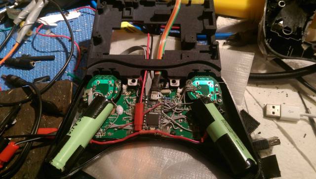
First step was to take apart and begin mutilating the controller. I figured the hand grips of the controller would be ideal places for batteries to fit, and they barely did (I had to cut away some of the joystick boards)
Early Layout
This was a very rough layout of components that changed dramatically as I improvised this entire project...
Power Supply Woes
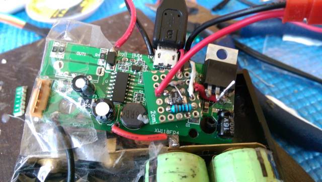
Sorting out the power supply system was one of the most annoying parts of this project. I needed a power controller that would seamlessly handle battery charging, battery protection, battery power supply and external power supply.
Other similar builds have used the Adafruit Powerboost (
https://learn.adafruit.com/adafruit-powerboost-1000c-load-share-usb-charge-boost/overview), and it's pretty much exactly what I needed except it's only rated for 1A power output, but the new Raspberry Pi 3 is a hungry beast and recommends a 2A supply.
Turns out that USB power banks are also quite ideal since they contain all that charging and protection circuitry, and some can output 2A. That mess above is one of those.
However there was an annoying issue with it since it's not designed to have both its output and input connected to the same thing (the Raspberry Pi in this case). The input and output of the power supply seemed to be isolated circuits (not common ground) and when the grounds were connected it caused the charger to enter some kind of semi-on state.
The solution was to use a mini relay to connect the charger input to the RPI when there is external power supplied.
Using controller player number lights as power indicators
The USB power bank also came with handy features like a power button and 4 charging/battery status indicator LEDs. The controller has a power button and 4 LEDs to indicate player number... what are the odds!
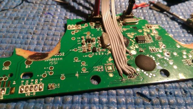
Here is the controller's mutilated circuit board with 4 wires connecting to the indicator LEDS (underneath) and one going to the power button pad.
Jumping into the future...
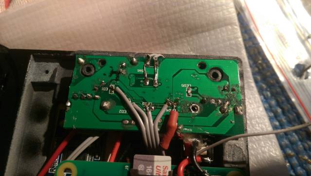
Here's how the other ends of those wires connect to the power button and LED outputs on the power supply board.
The Octopus
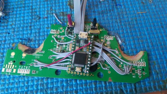
Unfortunately the Wii controller was Bluetooth-only and I couldn't even get it to work with anything other than an actual Wii. Therefore it was time to go for the brute force method of reading the button states with a Teensy (a mini powerful Arduino) which can act as a Joystick HID when connected to the RPI through USB.
Luckily the controller board had pads for all the button signals and here you can see them all wired up (except for the analogue joysticks).
Modified Pi
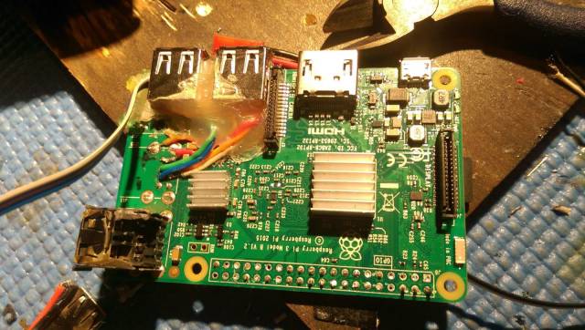
To slim things down a bit I removed the tall USB hubs, Ethernet port and GPIO pins from the RPI. I replaced two of them with thinner, side-by-side ports.
Screen
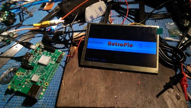
The screen is a 5" car reversing camera screen which takes the composite video feed from the Rpi It's meant to be powered by the 12V from a car battery, but actually has a switching regulator which converts this down to 3.3V. Unfortunately this built-in regulator didn't work too well with a 5V input voltage, so I had to bypass it and use another 5v to 3.3v regulator.
Originally I used an inefficient linear regulator to do this, but then found it got very hot due to the power it was dissipating (even with a heatsink), and replaced it with a better switching regulator.
Audio
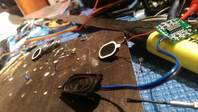
Here I'm testing some mini speakers with a small stereo amplifier. I found that the audio output from the RPi was just a bit low for my liking, apparently it's not meant to power headphones directly. So I decided to use USB soundcard, which also meant I then needed a USB hub to split the single remaining internal USB port (for the Teensy and the soundcard). This caused some issues with the USB hub dying when things got hot inside the case, so in hindsight it might of been best to just deal with the lower audio volume.
I put analogue volume control wheel in between the soundcard and the headphone jack, and the speakers are disconnected when headphones are plugged in.
The speakers are contained within the controller body and the gaps around the analogue joysticks conveniently allow sound to pass through, without having to make any extra holes.
CAD Time!
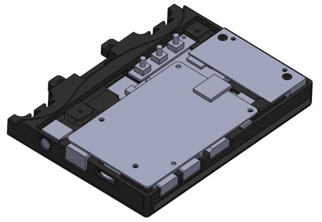
Now I needed to design the housing for the screen and other components, and how it would attach to the controller.
First step was to intricately measure every component and all their details and draw them up in Solidworks.
Then began the incredibly time consuming process of improvising a design to contain them all. In the end it worked out quite well and was very compact.
The screen slides into the slot underneath on the right.
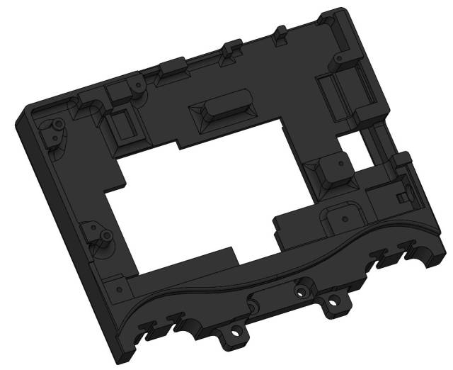
Without the bits
The screen goes behind this, facing the other way, with lips around the edge to hold it in place. The screen controlling board will be in that big gap in the middle.
I took an overhead photo of the controller to get the curved contour shape of its top, then scaled it and traced over it in Solidworks. The bottom of this screen holder will go inside the controller and be secured with screws & glue.
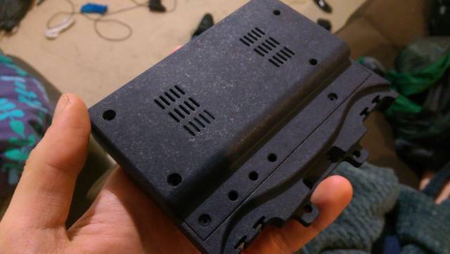
There is also a back plate which goes on top of this and has grills for ventilation.
From pixels to real life
I got the model SLS printed by an online 3D printing service, turned out very nicely. Here I'm just testing it out before sanding, priming & painting.
WIth Back cover
Wiring it up
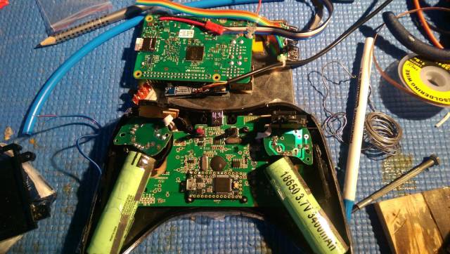
This is when it all starts to come together
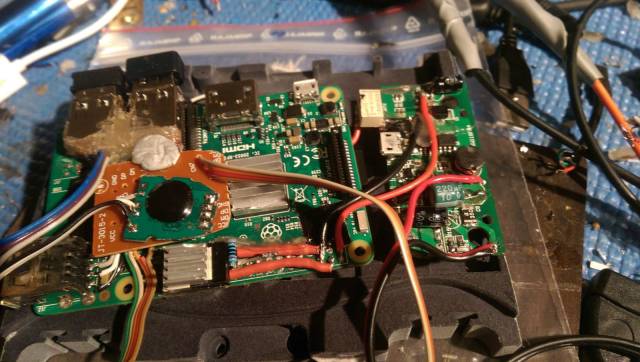
- Power supply board on the right, connected to RPi power input at the top through the relay (white box) and to the batteries down below
- USB hub (orange/brown board) with Teensy connected (rainbow ribbon)
- USB Soundcard (green with black blob) connected directly to USB hub, audio output wires coming off - Linear regulator for screen (down the bottom with red feet - to be replaced).
Finishing touches (take 1)
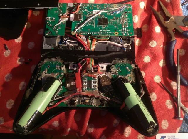
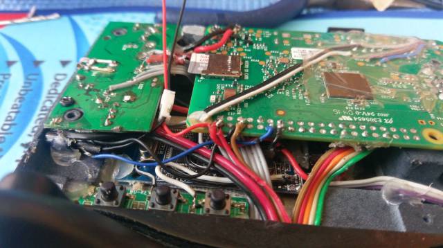
So this is pretty much what it looks like under the hood.
- The audio amplifier is sitting in the middle on top of the Teensy
- Speakers are on the sides next to batteries and thumb-stick boards
- There are two white plugs near the middle of the controller, next to the big red connector. They connect to the trigger buttons contained in the bottom half of the controller case.
Adding a Fan
When I finally got to use the device I discovered the USB Hub overheating issue.
Even though I put ventilation grills on the back cover, the components are just so dense inside and the back of the RPi effectively shields its CPU (underneath) from any air movement, so it get hot in there pretty quick.
I drilled some extra holes in the back case, some where the fan will go and a few more on the vertical face to allow air to. come out the side. I glued on some supporting screw holes to secure the fan to.
The fan fits nicely and isn't super obtrusive. Its power wires go through one of the cut-out slots and will be connected to a detachable plug.
I also drilled some holes through the RPi board itself (Where the USB ports used to be) to allow air to flow out from underneath. There is a strip of adhesive foam on the back cover which stops air from taking the easy path straight across to the opposite ventilation holes, forcing it to flow underneath the RPi where the CPU & heatsink is.
Fan Control
Everything is smart these days, even fans. I set it up so that it only turns on when the RPi CPU temperature gets too high. This is done with a Python script running on the RPi, reading temperature, and triggering a transistor to turn the fan on or off.
The fan works well to solve overheating problems and keeps the CPU temperature below 60C!
Time to Play!
Now it's time to catch up on all the old classics I never got a chance to try. I can also use it as a media centre with Kodi! This was a fun & rewarding project, and I think it's a very good, unique alternative to trying to design an ergonomic body from scratch. Finding a suitable controller that uses a standard USB connection and not having to use a USB hub would simplify things quite a lot. Thanks for reading!

